What Does Avf Stand for in Ecg
Of the many diagnostic tools used to screen for and evaluate cardiac abnormalities, the 12-lead electrocardiogram (ECG) is among the most basic. This inexpensive and noninvasive test provides a vast amount of information that assists in the diagnosis of conditions related to the heart's electrical activity. The ECG can also help evaluate myocardial ischemia and infarction, cardiomyopathy, pericarditis, and electrolyte disturbances. Although there are fundamental methods for interpretation, it is important to recognize that clinical correlation with the patient's signs and symptoms is essential.
 | Figure. No caption available. |
Using a systematic approach for interpreting ECGs is necessary. A specific framework helps the reader avoid diagnostic errors made by focusing on the ECG as a whole instead of the individual parts. A step-by-step analysis may also aid the clinician in recognizing both the obvious and subtle abnormalities that may help guide therapy.
Definition
The 12-lead ECG is a graphic representation of the electrical activity of the heart on two planes. The six limb leads (I, II, III, aVR, aVL, and aVF) provide a view of the heart from the edges of a frontal plane as if the heart were flat.1 The standard limb leads (I, II, and III) are bipolar and measure the electrical differences between the combination of three limbs: the right arm, left arm, and left foot. Bipolar leads have a positive and negative pole in which the electrical current is measured as electrons move from negative to positive. The augmented leads aVR, aVL, and aVF are unipolar and record the electrical difference between the right and left arms and the left foot utilizing a central negative lead (see Frontal Plane: Six Limb Leads).
The precordial leads, or V leads, represent the heart's orientation on a transverse plane, providing a three- dimensional view (see Precordial Views). They are placed anatom ically over areas of the left ventricle.1 Like the augmented leads, the precordial leads are unipolar with an electrically neutral center. Each individual V lead is the positive pole. The term "vector" describes the average direction of the heart's electrical depolarization from a negative to a positive pole. Imagining the heart's central orientation in relation to the limb and precordial leads and picturing where the positive poles are in each lead helps to understand why the individual leads represent specific areas of the heart. It is similar to taking pictures with a camera from different angles. V1 and V2 represent the intraventricular septum, V3 and V4 lie approximately over the anterior left ventricle, and V5 and V6 approximate the lateral left ventricular wall (see Summary of Lead Groupings). If there is a need to visualize the right ventricle or the posterior left ventricle, additional leads may be placed over those areas. With this in mind, there are a few rules that apply:
* When the average vector (direction of depolarization) is moving toward the positive pole of the electrode, the QRS complex will be upright on the ECG. Note that in lead II, the right arm is the negative pole and the left foot is the positive pole. This represents the general flow of electrical current through the heart, because, anatomically, the sino-atrial (SA) node is approximately at the right arm and the apex of the left ventricle is roughly on the same plane as the left foot. For this reason, one is able to see the P, QRS, and T waves best in lead II. Lead II is also the most commonly used lead for bedside monitoring.
* When the average vector is moving away from the positive pole of the electrode, the QRS complex is negative.
* When the average vector is moving perpendicular (at a right angle) to the positive pole of the electrode, the QRS will be biphasic (above and below the baseline).
* The more directly an electrical impulse comes toward or away from an electrode, the greater the amplitude or height of the QRS complex.
* The QRS complex in leads I, II, III, aVL, and aVF are normally upright, with aVR normally downward.
* The R wave in the precordial leads should progress from very small in V1 to very tall in V6. This is termed as "R-wave progression," and when not present, it suggests an abnormality that is most commonly an old anterior wall myocardial infarction (MI) or left bundle branch block (LBBB).
* A Q wave is the first negative deflection after the PR interval, and may be normal or abnormal depending on its size and shape.
Follow the Wave
The electrical activity of the heart is measured in millivolts and expressed in time and voltage on the ECG paper. This paper is divided into a grid with large squares measuring 5 mm or 0.2 second. Within the large boxes are smaller squares that are equivalent to 1 mm or 0.04 second (see ECG Grid). Waves and intervals that represent the cardiac cycle are recorded on the ECG paper (see Waves and Intervals). The P wave represents depolarization of the atria. The duration of the P wave should be less than 0.11 second and have an amplitude of less than 2 to 3 mm. The PR interval (PRI) represents the time for an impulse to travel from the SA node through the atrio-ventricular node (AV) and to the ventricles. Measured from the beginning of the P wave to the beginning of the QRS complex, the PRI should fall between 0.12 and 0.20 second (three to five small boxes). A PRI exceeding 0.20 second indicates a delay in conduction through the AV node representing a first-degree AV block, and a PRI of less than 0.12 second indicates a rapid conduction from the SA node to the ventricles suggesting bypass of the AV node (such as in Wolff-Parkinson-White syndrome). This abnormally shaped upward sloping P wave is sometimes referred to as a delta wave.
The QRS complex represents ventricular depolarization, and is the highest or deepest complex on the ECG. QRS measurements of greater than 25 mm (five large boxes) may be associated with ventricular enlargement, as in right or left ventricular hypertrophy (LVH). The duration of the QRS complex should not exceed 0.12 second; QRS complexes in excess of this measurement indicate a delay in the conduction through the ventricles as seen in right or LBBB. The QRS complex does not always have Q, R, and S waves. The Q wave is the first negative deflection after the PRI, the R wave is the first positive deflection, and the S wave is the negative deflection that follows the R wave.
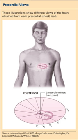 | Figure. Precordial Views. |
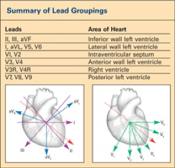 | Figure. Summary of Lead Groupings. |
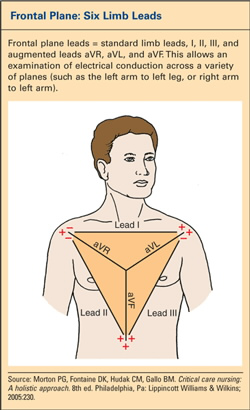 | Figure. Frontal Plane: Six Limb Leads. |
Q waves may or may not be of significance on the ECG. Deep Q waves in specific lead groupings can indicate an old MI, but may be normal when seen in isolated leads. For a Q wave to be significant or pathological, it must be found in the lead groupings associated with an area of infarct, and must be greater than 0.04 second wide or at least one-third the height of the QRS complex. Q waves that are smaller than these measurements are generally clinically insignificant.
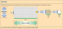 | Figure. ECG Grid. |
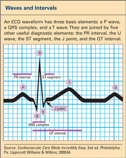 | Figure. Waves and Intervals. |
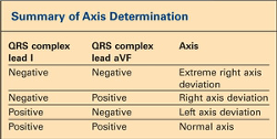 | Table. Summary of Axis Determination |
The ST segment represents the time from completion of ventricular depolarization to repolarization. ST segments are measured in relation to the baseline or isoelectric line, which is between the end of the P wave to the beginning of the QRS complex. The J point is the junction of the QRS complex and the ST segment.1 This is an important area to assess when evaluating for ST segment elevation or depression. ST segment elevation may indicate acute myocardial injury, and ST segment depression may be an indication of myocardial ischemia. The ST segment and T wave changes are found in leads associated with ischemia and injury in a specific area of the heart. J points should be at least 1 to 2 mm above the baseline in at least two contiguous leads to be considered significant.
The T wave corresponds to ventricular repolarization and normally follows the direction (positive or negative) of the QRS complex in most leads. A T wave with high amplitude may be seen in hyperkalemia or very early MI. Inverted T waves, especially if they are symmetrically inverted, may suggest non-ST elevation myocardial infarction (NSTEMI). However, variations in the ST segment and T-wave morphology can be seen in a variety of conditions, including ventricular hypertrophy, bundle branch block (BBB), myocardial ischemia, or resolving MI.
The QT interval is measured from the beginning of the QRS to the end of the T wave. It is inversely related to heart rate, and is influenced by the patient's age and sex. The "QTc" implies a QT interval that has been corrected for heart rate. There are tables available to determine appropriate QT intervals for given heart rates, but an easy rule may be applied: the QT interval is probably prolonged if it exceeds one-half of the R-R interval in heart rates from 60 to 100 beats per minute.2 A prolonged QT interval may result from electrolyte abnormalities or a variety of commonly used drugs, such as antiarrhythmic agents, psychotropic drugs, and antibiotics. A shortened QT interval may be related to the presence of hypercalcemia, digoxin toxicity, or thyrotoxicosis.
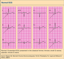 | Figure. Normal ECG. |
Axis
Axis refers to the direction of the main vector in which depolarization occurs. A wave that travels toward a positive lead will result in an upward or positive deflection (tracing) on the ECG, and a wave traveling away from a positive lead will result in a downward or negative deflection. Waves that travel at 90 degrees or at a right angle to a particular lead will be biphasic, appearing above and below the baseline or isoele ctric line.
The mean axis represents the sum of the vectors, or direction of depolarization to produce as single vector. In a heart with normal axis, the summed vector should be point ing in a downward and leftward direction, as the conduction starts in the SA node (near the right shoulder) and travels downward and leftward to the ventricles. Axis is actually expressed in degrees, but it is usually adequate in the clinical setting to know in general if an axis deviation is present. Only the first six leads are used to determine axis; the precordial leads are not utilized. An axis deviation suggests that the electrical forces do not follow the normal direction of depolarization from right shoulder to left foot. There are multiple ways to determine an accurate measurement of axis in degrees, but a simple method to assess the axis in general terms has been determined (see Summary of Axis Determination).
Some common causes of left axis deviation include LBBB, left anterior hemiblock, LVH, and inferior wall MI. Right axis deviation may include right bundle branch block (RBBB); left posterior hemiblock; right ventricular hypertrophy; and pulmonary disease such as chronic obstructive pulmonary disease, pulmonary hypertension, or pulmonary embolus. Axis deviation as an isolated finding is not necessarily important. The ECG reader should note that it is present, and then correlate its significance in the clinical setting.
The Normal ECG
When analyzing the ECG, it is important to know what is normal (see Normal ECG). Remember that the first six leads should all be upright (except aVR), and in the precordial leads the R wave progresses from small to tall across the precordium. The ECG should always be first evaluated for rate and rhythm and then examined for individual waves, intervals, and patterns.
ST and T Wave Changes
Injury, Ischemia, and Infarction
When a patient experiences chest pain, recognizing ECG changes consistent with myocardial ischemia, injury, and infarction are critical in facilitating rapid treatment to reestablish blood supply and salvage vulnerable heart muscle. Ischemia and injury are often reversible with treatment. However, when the blood supply is interrupted for a prolonged period of time, infarction may occur, resulting in scarred or necrotic tissue. STEMI is usually caused by a thrombus, though a small percentage may be caused by vasospasm or embolus. The left ventricle is referred as the site of infarction unless otherwise specified. The right ventricular infarction may occur in conjunction with a left ventricular inferior wall infarct because both areas are supplied by the right coronary artery. The appearance of pathological Q waves (greater than 0.04 second wide or greater than one-third the height of the QRS complex) implies transmural MI. Further evaluation of the ECG for changes associated with ischemia and infarction involves examination of the ST segment and T waves.
Myocardial ischemia implies a decreased blood supply to an area or areas of the heart, and is reversible once blood flow is restored. It is reflected as T wave inversion or ST segment depression on the ECG. Abnormal T waves that are suggestive of NSTEMI are generally symmetrically inverted and often deep.
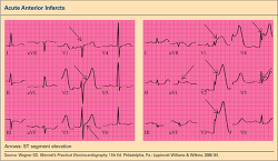 | Figure. Acute Anterior Infarcts. |
Acute myocardial injury is indicated by ST segment elevation, and like ischemia, is reversible with rapid treatment. Remember that injury is reversible with treatment, but infarction is not. A J point elevation in leads V2 through V4 indicates acute injury in the anterior wall. Often, reciprocal changes (ST depression) appear in other leads. Acute injury in the inferior wall with a pattern of elevated J points and ST segment elevation in leads II, III, and aVF, with reciprocal ST depression in the anterior leads, usually results from an occluded right coronary artery (see Acute Anterior Infarcts and Acute Inferior Infarcts). However, in about 10% of patients, it involves the left circumflex artery. These patients are considered to have left dominant coronary circulation.1
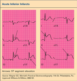 | Figure. Acute Inferior Infarcts. |
Elevated J points and ST segment elevation in the precordial leads V2 through V6, as well as in leads I and aVL, indicate acute anterolateral wall injury. Deep Q waves suggest that the possibility of scarring has already occurred in the anterior wall. Also, ST elevation in leads I and aVL indicate lateral wall injury. Anterior wall infarct involves the left anterior descending coronary artery; lateral wall injury is often caused by disease in the left circumflex artery.
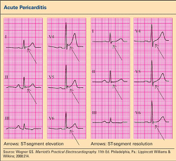 | Figure. Acute Pericarditis. |
In the acute stages of MI, ST segments generally elevate within minutes or hours and may stay elevated for several days. During evolution of the MI, the ST segments slowly migrate toward the baseline and the T waves become inverted. Over the next few weeks, the T waves usually return to normal. Q waves may or may not evolve.
Other common causes for ST segment and T wave abnormalities include LVH, pericarditis, early repolarization, and BBBs. Less frequently seen causes include electrolyte abnormalities and central nervous system abnormalities.
LVH
ST-T wave abnormalities associated with LVH most commonly occur in the anterolateral leads, and are typically seen as a horizontal or downsloping ST segment and inverted T wave . This pattern is often referred to as "strain" and thought to be related to conduction delays through the thickened diameter of the muscle wall. In trying to distinguish ST-T wave changes associated with LVH from ischemia, QRS voltage criteria may be helpful.
Pericarditis
Pericarditis, an inflammation of the pericardium, typically produces diffuse ST segment elevation in most leads. Often, these changes may be confused with other causes for ST elevation, especially acute MI (AMI) and early repolarization. Again, as with any ECG evaluation, it is critical to evaluate the clinical context in which the ECG abnormalities occur. Pericarditis typically produces a friction rub that is heard on auscultation; the pain is generally sharp and stabbing in nature, and is often relieved by anti-inflammatory medications (see Acute Pericarditis).
Early repolarization
Early repolarization is a normal variant and is not indicative of coronary disease. It often occurs in young, healthy individuals, but in the setting of chest pain, it may be confused with myocardial injury. Most of the ST changes that occur in early repolarization involve the precordial leads with J point elevation and a pattern of concave upward ST segments.
BBB
Electrical impulses reach the ventricles by way of AV junction. Depolarization then occurs in a wave-like fashion in the ventricles by way of the right and left bundle branches. The left bundle branch bifurcates into the anterior and posterior branches, whereas the right bundle branch is undivided. Any condition that affects the normal electrical conduction in the ventricles will cause a delay, resulting in a widening of the QRS complex. The presence of widened QRS complexes in all or most leads should alert the interpreter to the presence of a BBB. The next step is to determine in which branch (or branches) the conduction is delayed or blocked.
Once widened, QRS complexes are identified. An easy process exists to differentiate between RBBB and LBBB by evaluating three key leads, specifically leads I, V1, and V6. After an electrical impulse leaves the AV node, it normally travels downward and activates the intraventricular septum in a left to right direction. Since V1 is to the right of the septum and the impulse is coming toward it, a small R wave normally appears in V1. In LBBB, depolarization occurs from right to left and away from the V1 lead, resulting in the loss of the R wave. Therefore, in LBBB, the first deflection in V1 will be negative (a Q wave) rather than the normal R wave that is usually seen.
In RBBB, the impulse travels normally down the left bundle branch, activating the septum and then the left ventricle. A normal R wave is therefore produced in V1, since the septum is activated normally. Once the left ventricular depolarization has occurred, the impulse then spreads across to the right ventricle (moving toward V1) producing a second positive deflection. This is the typical "rabbit ears" pattern of RBBB often seen in V1. The second R wave is also sometimes referred to as R prime. The QRS complexes in incomplete RBBB or LBBB have similar morphology, but they are not as wide (less than 0.12 second). These incomplete blocks are sometimes referred to as intraventricular conduction defects.
Hemi-blocks, or fascicular blocks, may occur in the anterior or posterior branches of the left bundle branch. They do not produce a widening of the QRS complex. They are recognized by the axis changes that are produced. In general, a left anterior hemi-block causes a left axis deviation, and a left posterior hemi-block produces right axis deviation.
Because the depolarization sequence in BBBs is abnormal, repolarization may also be affected, producing ST segment and T wave abnormalities. As a general rule, the orientation of the ST segment and T wave in BBB is opposite to that of the terminal QRS deflection in each of the three key leads. An ST segment may appear elevated in the presence of BBB, especially with LBBB, and therefore the diagnosis of AMI should be made with caution in the presence of LBBB (see Summary of Changes in Key Leads Seen in RBBB and LBBB).
The key to sound ECG interpretation is using a systematic method and lots of practice.
 | Table. Summary of Changes in Key Leads Seen in RBBB and LBBB |
REFERENCES
What Does Avf Stand for in Ecg
Source: https://www.nursingcenter.com/ce_articleprint?an=00006205-200810000-00008
0 Response to "What Does Avf Stand for in Ecg"
Post a Comment